1. Introduction
1.1 Project Overview
The goal of this project is to design and develop a wearable heart-rate sensor with a compact form factor and wireless data transmission capabilities. The device will use low-power electronics to optimize battery life while providing accurate heart-rate monitoring.
Additionally, this wearable device will enable our clinical research group to collect data from UCLA athletes, analyze it, and use the data for research journal publications. This process includes researchers learning how to design the PCB according to project goals, assembling, and testing the final product.
1.2 Objectives
-
Design a small, wearable heart-rate monitor.
-
Incorporate wireless data transfer (Bluetooth or Wi-Fi).
-
Optimize power consumption using sleep modes and power gating.
-
Ensure real-time processing through edge computing.
-
Minimize device footprint for user comfort.
-
Integrate additional sensors such as an oxygen sensor and a gyroscope.
-
Develop a structured workflow for PCB design, assembly, and testing.
2. System Design
2.1 Hardware Architecture
The wearable device consists of the following key components:
-
Microcontroller Unit (MCU): Manages data processing and connectivity.
-
Optical Sensor (PPG): Measures volumetric changes in blood circulation.
-
Oxygen Sensor: Measures blood oxygen saturation (SpO2).
-
Gyroscope: Tracks movement and orientation.
-
Battery Unit: Provides power with optimized consumption techniques.
-
Wireless Module (Bluetooth/Wi-Fi): Supports Bluetooth and/or Wi-Fi connectivity.
-
RF Switch: Enables frequency sharing for dual connectivity.
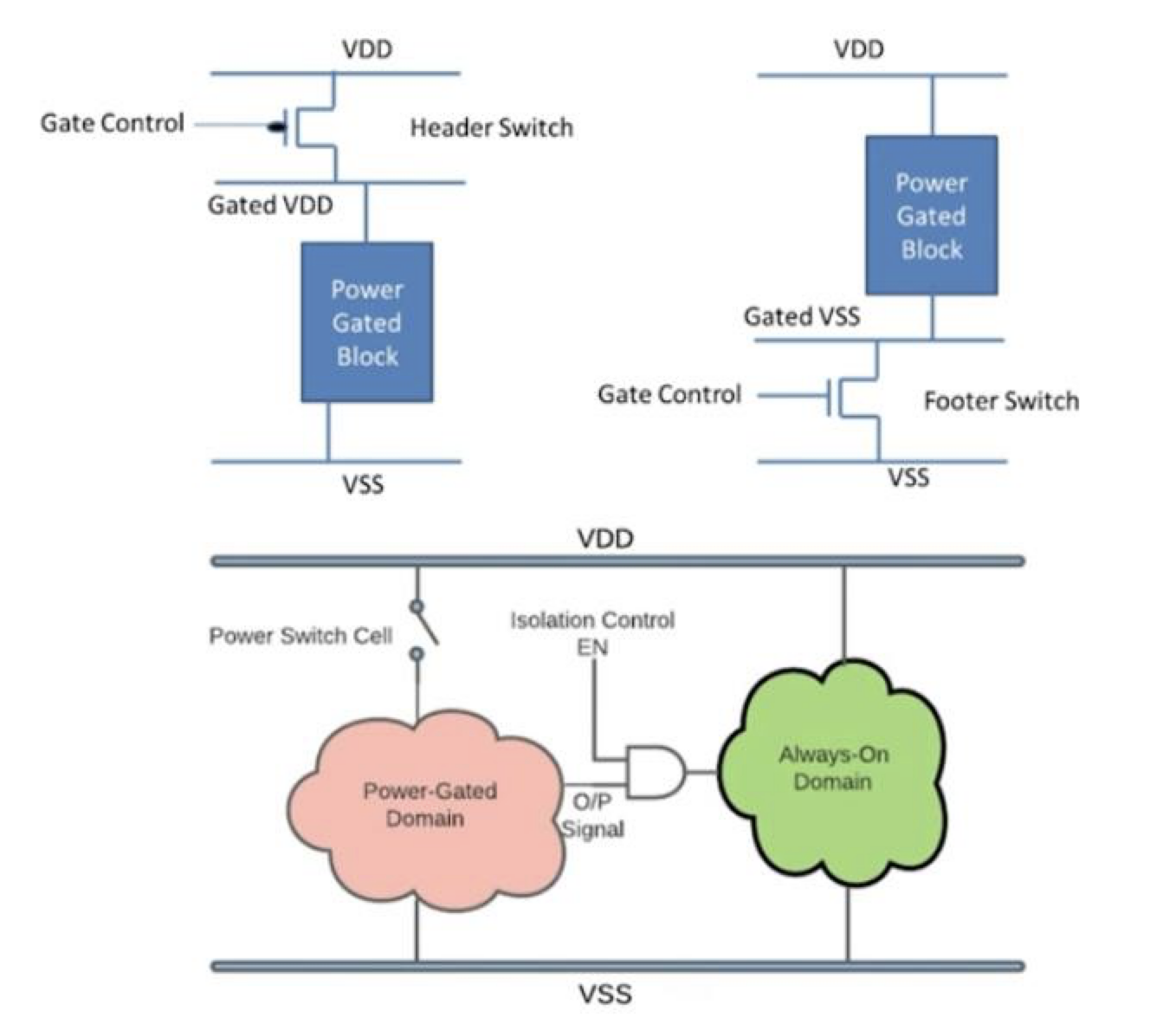
2.2 Power Management
Power consumption is a critical factor in wearable devices. The following techniques are implemented:
-
Power Gating: Disables non-essential components when inactive.
-
Sleep Modes: Reduces power usage when heart rate measurement is not required.
-
Efficient Connectivity: Optimizes data transmission tradeoff between power consumption and data rate.
3. Sensing Methodology
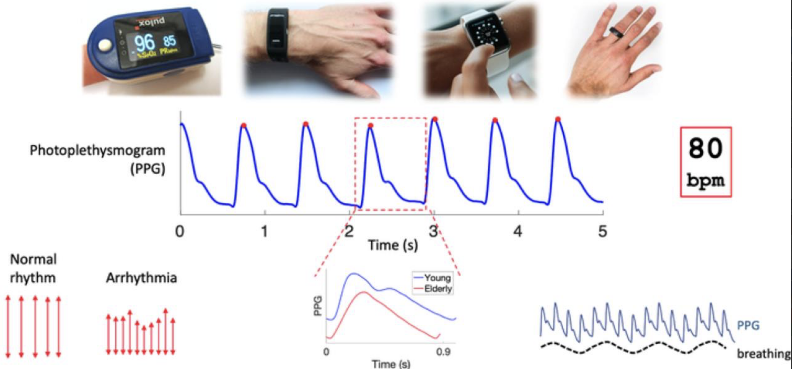
3.1 Photoplethysmography (PPG)
The heart-rate sensor utilizes PPG, an optical technique that detects volumetric blood flow variations in peripheral circulation. It consists of an LED light source and a photodetector to measure reflected or transmitted light intensity variations.
3.2 Oxygen Sensor
The integrated oxygen sensor measures blood oxygen saturation (SpO2) using optical absorption techniques similar to PPG.
3.3 Gyroscope
The gyroscope sensor detects motion and orientation, allowing for movement-based tracking and activity monitoring.
3.4 Edge Processing
To optimize performance and power consumption, the system will:
-
Process heart-rate, oxygen, and movement data locally before transmission.
-
Filter and extract only relevant health and motion information instead of raw signals.
4. Wireless Connectivity
4.1 Connectivity Options
The device will use Bluetooth and/or Wi-Fi for data transmission to a smartphone application. The choice between them depends on:
-
Range Requirements: Bluetooth for short-range, Wi-Fi for longer range.
-
Data Rate Needs: Higher data rates require higher power consumption.
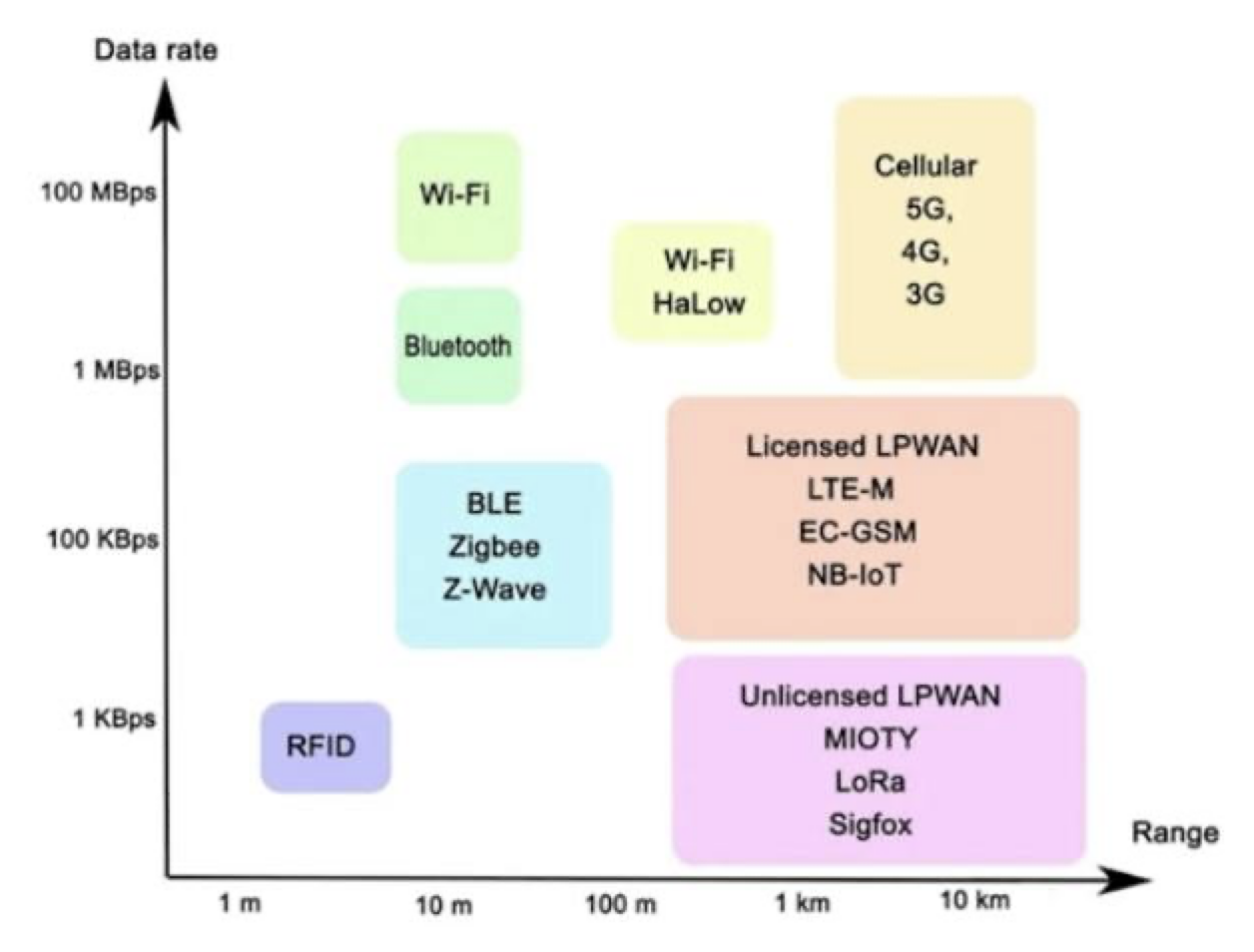
Since our device will use Bluetooth or Wi-Fi to connect to a smartphone, we’ll be focusing on those respective frequency ranges.
Higher data rates will also lead to higher power consumption, therefore we must optimize the tradeoff between trying to have as much data possible exposed over bluetooth while not consuming too much power.
4.2 Frequency Considerations
Since Bluetooth and Wi-Fi operate on the same frequency band (2.4 GHz), careful module selection is necessary:
-
Pre-Certified Modules: Ensures compliance with regulatory standards.
-
RF Switches: Allows the device to share a single antenna for multiple wireless protocols, minimizing device size.
5. Mechanical Design
5.1 Compact Footprint
The wearable device’s housing is designed to be:
-
Small and lightweight for user comfort.
-
Ergonomically optimized for secure placement on the body.
6. Project Milestones
To ensure successful project completion, the following milestones are established:
-
Research & Planning (Month 1-2)
- Define technical specifications.
- Select components (MCU, sensors, connectivity modules).
- Establish power management strategies.
-
PCB Design & Prototyping (Month 3-4)
- Learn PCB design principles.
- Design and simulate PCB layout.
- Manufacture and assemble initial prototypes.
-
Firmware Development & Testing (Month 5-6)
- Implement sensor data acquisition and edge processing.
- Develop wireless communication protocols.
- Test power efficiency and sensor accuracy.
-
Data Collection & Analysis (Month 7-8)
- Deploy the device with UCLA athletes.
- Collect and analyze physiological data.
- Refine sensor accuracy and device performance.
-
Final Testing & Journal Submission (Month 9-10)
- Conduct extensive validation trials.
- Finalize research findings and submit for publication.
7. Future Improvements
- Evaluate different wireless protocols for optimized power efficiency.
- Explore AI-based data processing and analytics for improved heart-rate accuracy and user interface experience.
- Conduct extensive user testing to refine design and performance.
- Improve gyroscope-based motion tracking for enhanced activity recognition.
8. Bill of Materials
| Item # | Component | Description | Quantity | Notes |
| 1 | Microcontroller Unit (MCU) | Manages data processing, sensor interface, and wireless communication. | 1 | [Model TBD] Need to choose a low-power MCU with sufficient processing power, memory, and I/O pins. (ARM Cortex-M series??). Must be compatible with selected sensors and wireless module… |
| 2 | Optical Sensor (PPG) | Measures heart rate via photoplethysmography. | 1 | [Model TBD] Select a PPG sensor with appropriate wavelength and sensitivity for accurate heart rate detection. Consider sensors with integrated ambient light rejection… |
| 3 | Oxygen Sensor (SpO2) | Measures blood oxygen saturation. | 1 | [Model TBD] Select an SpO2 sensor compatible with the PPG sensor, potentially integrated within the same module. Ensure accuracy within the expected SpO2 range (Need to determine this range). |
| 4 | Gyroscope | Detects motion and orientation. | 1 | [Model TBD] Choose a gyroscope with sufficient sensitivity and range for activity tracking. Consider a 6-axis or 9-axis IMU that combines gyroscope, accelerometer, and magnetometer… |
| 5 | Battery Unit | Provides power to the device. | 1 | [Model TBD] Select a rechargeable Lithium Polymer (LiPo) battery with appropriate capacity for desired battery life. Consider a battery management IC (BMIC) for charging and protection. |
| 6 | Wireless Module (Bluetooth/Wi-Fi) | Enables wireless data transmission to a smartphone or other device. | 1 | [Model TBD] Choose either Bluetooth Low Energy (BLE) or Wi-Fi module based on range, data rate, and power consumption requirements (Determine these requirements). Look for pre-certified modules to simplify regulatory compliance… |
| 7 | RF Switch | Allows the device to share a single antenna for multiple wireless protocols (if using both Bluetooth and Wi-Fi). | 1 | [Model TBD] If using both Bluetooth and Wi-Fi, select an RF switch with low insertion loss and high isolation… |
| 8 | PCB | Printed circuit board for mounting and connecting components. | 1 | Custom designed PCB based on component selection and desired form factor… |
| 9 | Resistors | Various resistors for pull-up, current limiting, and voltage division. | Varies | [Values TBD] Values determined by circuit design. |
| 10 | Capacitors | Various capacitors for filtering, decoupling, and energy storage. | Varies | [Values TBD] Values determined by circuit design. |
| 11 | Inductors | Optional inductors for filtering or power management. | Varies | [Values TBD] Values determined by circuit design. |
| 12 | Connectors | Connectors for battery, programming, and other external interfaces (if needed). | Varies | [Type TBD] Select appropriate connectors based on design requirements. |
| 13 | Enclosure | Housing for the device, providing protection and a wearable form factor. | 1 | [Material/Design TBD] Consider 3D printing or custom molding for the enclosure. Ensure ergonomic design for comfortable wear. |
| 14 | LEDs | Status indicator LEDs (optional). | Varies | [Color/Type TBD] Select appropriate LEDs based on desired indication and power consumption. |
| 15 | Conductive Fabric/Electrodes | For reliable contact with the skin for PPG and SpO2 measurements. | Varies | Select medical-grade conductive fabric or electrodes suitable for long-term skin contact. |
| 16 | Programming Header/Connector | Used for programming the MCU | 1 | Select appropriate connector/header based on the programmer/debugger used. |
Questions:
When choosing connectivity modules, we must choose pre-certified modules. - Q. WHY??
Another consideration that we must look after is if we are going to combine Bluetooth or Wifi, we must consider that they are on the same frequency. By using RF switches to share the same antena, this will enable us to have a small footprint device. - Q. WHY??
Q. Will I be using Bluetooth, Wi-Fi, or both??